Objectives
- To make a smart alert system for regulator based machines.
- To make use of LEDs to display different value limits reached on regulator.
- To make use of buzzer to indicated maximum value reached on those different limits.
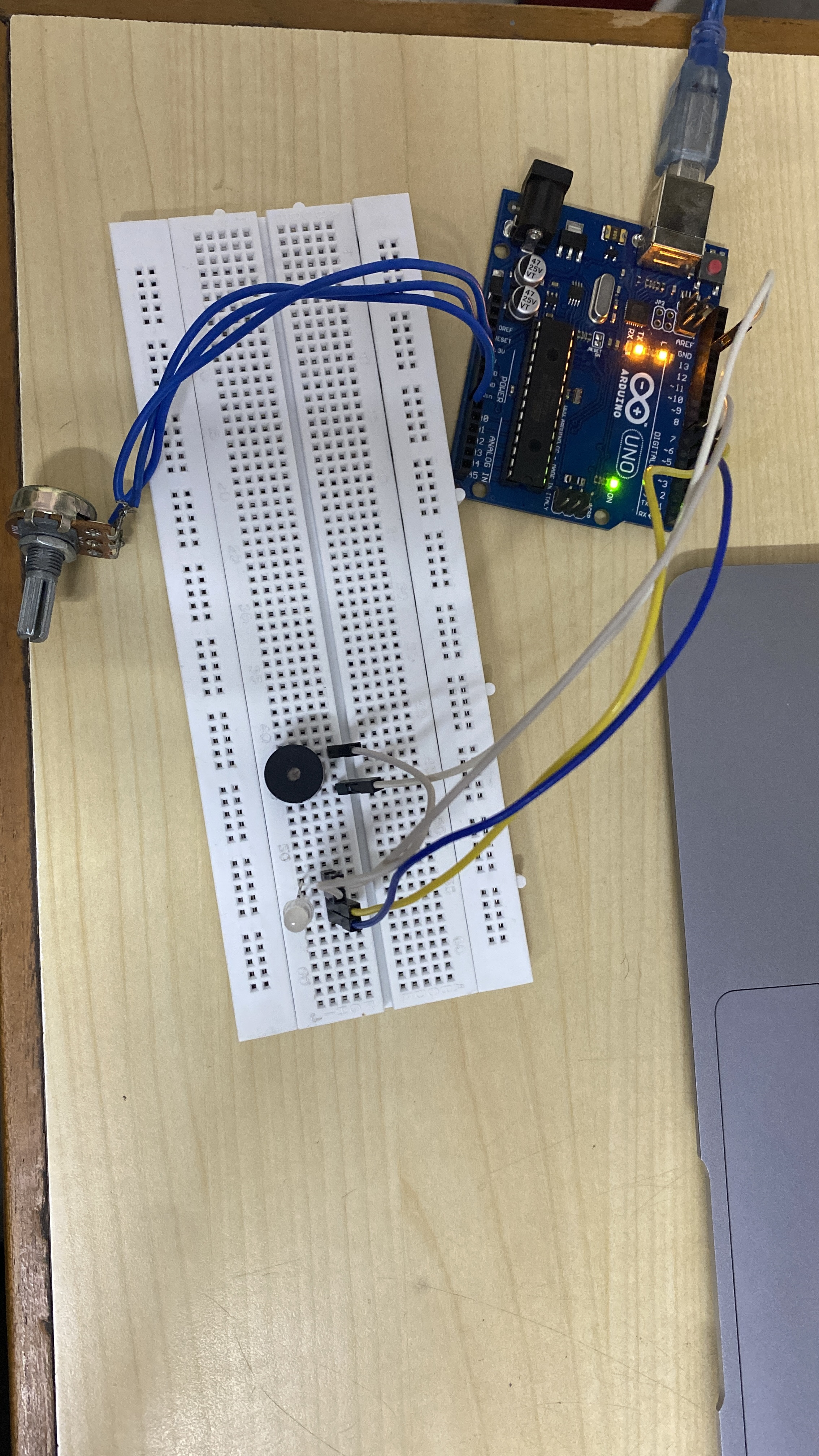
Devices/Components used
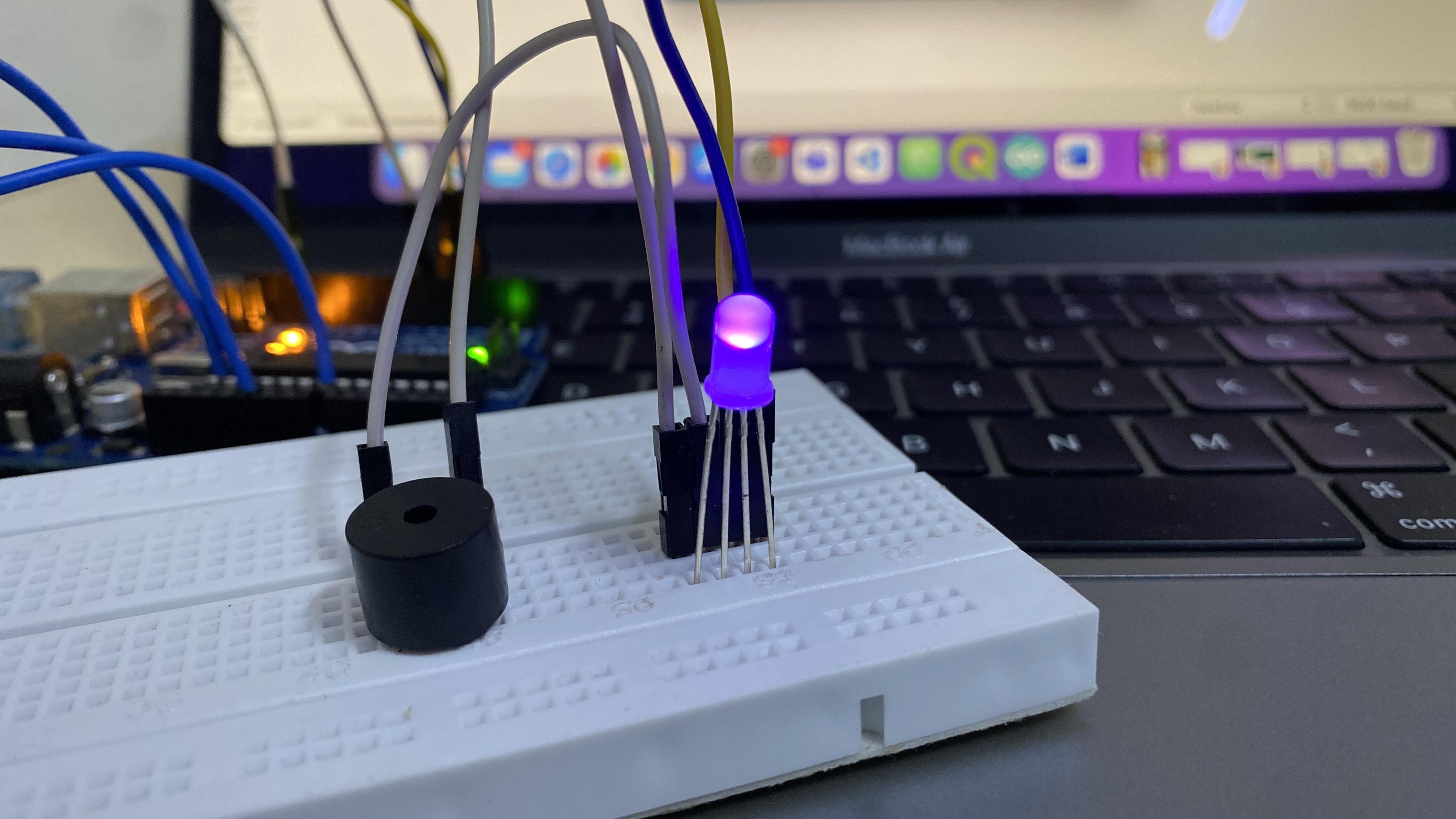
- Arduino UNO : Controller
- Potentiometer : Analog Input
- Buzzer : Output
- RGB LED : Output
- Breadboard
- M-M Connectors
Software Used : Arduino IDE
Circuit and Wiring
Arduino Code
For Arduino Code click here.
#define BLUE 3
#define GREEN 5
#define RED 6

// the setup routine runs once when you press reset:
void setup() {
  // initialize serial communication at 9600 bits per second:
  Serial.begin(9600);
  pinMode(RED, OUTPUT);
  pinMode(GREEN, OUTPUT);
  pinMode(BLUE, OUTPUT);
}

// the loop routine runs over and over again forever:
void loop() {
  // read the input on analog pin 0:
  int sensorValue = analogRead(A0);
  // print out the value you read:
  Serial.println(sensorValue);

  if (sensorValue >=0 && sensorValue <256) {
    RGB_color(sensorValue%255, 0, 0);
  }
  else if (sensorValue >=256 && sensorValue <511) {
    RGB_color(0, sensorValue%255, 0);
  }
  else if (sensorValue >=511 && sensorValue <766) {
    RGB_color(0, 0,sensorValue%255);
  }
  else {
    RGB_color(sensorValue%255,sensorValue%255, sensorValue%255);
  }

  //delay(1000);        // delay in between reads for stability
}


void RGB_color(int red_light_value, int green_light_value, int blue_light_value)
 {
  analogWrite(RED, red_light_value);
  analogWrite(GREEN, green_light_value);
  analogWrite(BLUE, blue_light_value);
}
#define BLUE 3
#define GREEN 5
#define RED 6
// the setup routine runs once when you press reset:
void setup() {
// initialize serial communication at 9600 bits per second:
Serial.begin(9600);
pinMode(RED, OUTPUT);
pinMode(GREEN, OUTPUT);
pinMode(BLUE, OUTPUT);
}
// the loop routine runs over and over again forever:
void loop() {
// read the input on analog pin 0:
int sensorValue = analogRead(A0);
// print out the value you read:
Serial.println(sensorValue);
if (sensorValue >=0 && sensorValue <256) {
RGB_color(sensorValue%255, 0, 0);
}
else if (sensorValue >=256 && sensorValue <511) {
RGB_color(0, sensorValue%255, 0);
}
else if (sensorValue >=511 && sensorValue <766) {
RGB_color(0, 0,sensorValue%255);
}
else {
RGB_color(sensorValue%255,sensorValue%255, sensorValue%255);
}
//delay(1000); // delay in between reads for stability
}
void RGB_color(int red_light_value, int green_light_value, int blue_light_value)
{
analogWrite(RED, red_light_value);
analogWrite(GREEN, green_light_value);
analogWrite(BLUE, blue_light_value);
}